Google Glass 3D optical layout reconstruction, based on teardown information
中文读者请看 Google Glass 使用了哪种显示技术?具体是怎么实现的? http://www.zhihu.com/question/20276179
Chinese reader please hit this: http://www.zhihu.com/question/20276179
—————————————————————————————————
Since my major is Optical Engineering, I am very exciting about Google Glass, and also keep eyes on it from the beginning. Several months after introduced glass, the explore edition hit the developer. Some of them make a teardown test, even it was not a completely teardown, we can get lots of information from it.
This post is an original “research” article, based on teardown information that I can find in the Internet. Shows how we can get an almost complete optical layout from the information.
—————————————————————————————————
First, according to several hackers and developers[1][2][3][4][5], the hardware configuration is:
CPU: TI OMAP4430
RAM: 682 MB
Display resolution: 640 x 360 pixel (very important information)
Internal storage: 16 GByte
Sensors:
Invensense MPU9150=Invensense MPU6050 (3 axis gyroscope + 3 axis accelerometer)+Asahi Kasei AKM8975 (3 axis geomagnetic sensor(compass))
LiteON LTR-506ALS rear-facing sensor(RFS) or “proximity” sensor
One more thing, glass support “wink” command, up to 20 winks!
So here is main information source from teardown test from Bill Detwiler [1] [5] <- hit it, very good articles. He opened the front shell ……

Figure 1 cracking open Glass from Bill Detwiler and TechRepublic. I think (a) the flexible PCB with white characters is the interconnection between these module; (b) the small connector near the prism is connected to RGB LED light source.
And here is a close view of the most interesting part of Glass,

Figure 2 cracking open Glass from Bill Detwiler and TechRepublic. I think (a) there is a shaft/axis that allow it to rotate; (b) a “cellphone” camera, don’t know the part number.
And another view,

Figure 3 cracking open Glass from Bill Detwiler and TechRepublic. I think the prism is NOT embed by the part (in black), it should be bonding by optical/mechanical adhesive.
and the bottom view,

Figure 4 cracking open Glass from Bill Detwiler and TechRepublic. I think the interconnection near the prism is for RGB LED.
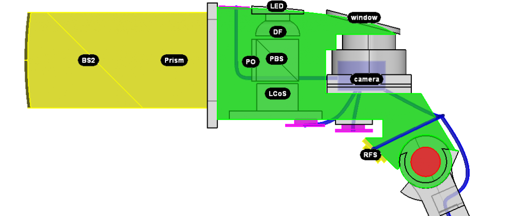
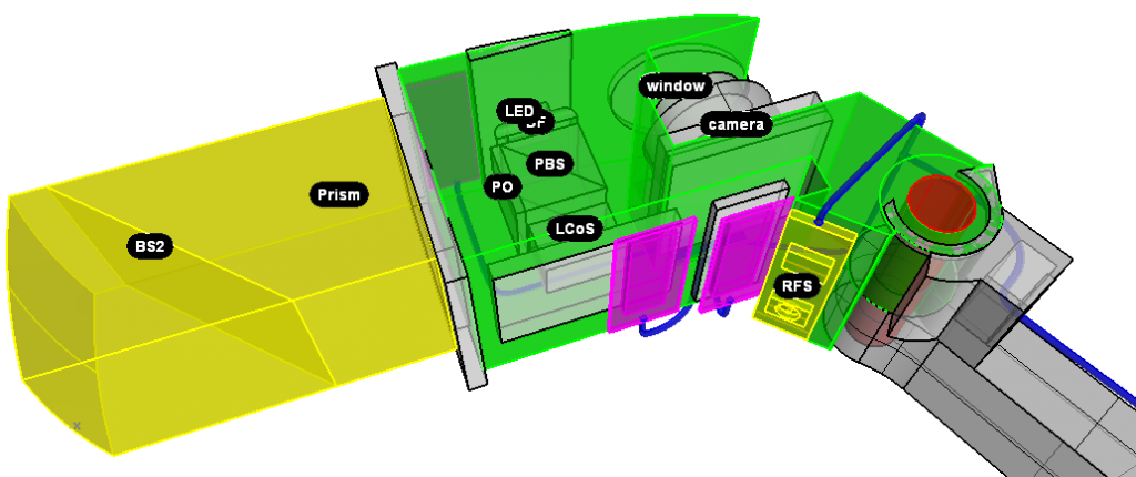
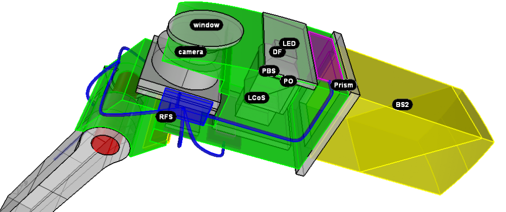
Based on these information and some analysis listed below, i can get the optical layout of Glass, in 3D shown below.
Here, BS2 = beam splitter 2, PO = polarizer, DF = diffuser, PBS = polarized beam splitter, LCoS = Liquid crystal on silicon micro display unit. RFS = rear-facing sensor.
(a) based on the size limitations and the resolution, and Karl Guttag’s post about Glass [6], i think Glass using a Himax Color Sequential LCOS display, part number HX7309[7]. It has a resolution of 640 x 360, active area of 4.8 x 2.7 mm, this size is suitable for Glass. But it needs a RGB LED, How?
(b) well, if you take a look at Figure 4, near the prism, the flexible PCB interconnection, if the light source is White LED (i mean, blue LED chip + yellow phosphor), it only need TWO wires. But there are more than 2 wires, i think there are 4, or 5 (look at the shade of wires carefully, it can tell). A RGB LED typical has 4 wires (common cathode). So the RGB LED can lighting sequential + RGB image display sequential = full color display. This layout also the reason of sequential Red, Green, and Blue Fields checkout Karl Guttag’s post about Glass [6], and we can see full color by our eyes but using camera to capture the image of Glass, sometimes we seen a separate color, R,G,B, just like this one [8]. Because the exposure time is so short in daytime, make it only capture red “status” of display.
(c) usually, the chip position of RGB LED is different, in order to get a uniform light field, i think there is a diffuser in front of the second optics of LED.
(d) there is NO mini projection lens between prism and PBS. Because, if there is a lens, when we capture the image in front the Glass, it’ll rotate 180 degree. Because it should be long enough to establish a real image, which is 180 degree rotation refer to object.
(e) in order get slightly down slope light direction, it need to move display unit a little bit higher refer to its optical axis. I didn’t draw it. But i believe it is true.
Hope i can get one Glass. Really cool, especially in optical engineering, it’s a fantastic product.
Reference
[1] http://www.techrepublic.com/photos/cracking-open-the-google-glass-explorer-edition/6416082?seq=40&tag=thumbnail-view-selector;get-photo-roto
[2] http://thecodeartist.blogspot.com/2013/05/sensors-on-google-glass.html
[3] https://plus.google.com/108304992255149838420/posts/GwvagwVN6Hz
[4] https://developers.google.com/glass/ui-guidelines
[5] http://news.cnet.com/8301-17938_105-57584381-1/google-glass-explorer-edition-teardown-reveals-hits-and-misses-on-repairability/
[6] http://www.kguttag.com/2013/03/11/google-glass-is-using-field-sequential-color-fsc-lcos-likely-himax/
[7] http://www.himaxdisplay.com/en/product/HX7309.asp
[8] http://www.technologyreview.com/view/514696/want-to-see-what-its-like-to-wear-google-glass/


